
How to Stay on Budget with Utility Steel Structure Projects
Steel structures offer strength, durability, and long-term value. However, one of the biggest...


In marketing, catchy titles and inspiring phrases are my forte. However, when it comes to numbers, let’s just say I rely heavily on my calculator app. But with civil engineers, numbers are their friends. There’s this “numbers game”, if you will, that they play daily. When designing steel structures, engineers first develop the loads and then apply the loads in their design. Once loads are applied, they are tasked with finding the best possible combination of steel members and connection types while paying special attention to section properties, weights, aesthetics, constructability, etc.
Pretty straight forward, right? Well not exactly. There are two major things that the engineer must consider: first, make sure the structure doesn’t over deflect, and second, make sure it doesn’t over stress. If the steel structure experiences over deflection, especially in a substation, this could potentially damage the equipment that are mounted on the structure. If the structure over stresses, it could cause things like yielding, cracking or even falling down.
It’s important to take all possible loading scenarios into account, such as combined ice and wind loads, extreme wind loads, earthquake loads or wind-induced oscillations, and apply them to ensure the structures stay within their set limits required by code, contract documents, customer specifications, etc. These structures can consist of an assortment of pipe, channels, wide flanges, square tubes, or even custom shapes like tapered tubular poly members.
While it’s important to find the best possible combination of section properties, an engineer should also always be looking at the most economical choice when designing the structure for the customer. Steel fabricators can design structures from standard shape steel, all the way to tapered tubular steel, so it’s important that the engineer takes a good look at the entire picture, because remember, at times there is a direct correlation between heavier steel and higher costs. This is where the numbers game comes into play.
So, let’s say an engineer is designing a basic shape like a square tube, also known as hollow structural sections, they might start out with HSS 6x6x3/16 and keep increasing the thickness, which immediately helps with the stress but doesn’t help as much with deflection. At this point they need to start paying attention to the section properties by finding the best possible combination between things like the I Value (moment of inertia) and the S Value (section modules) while watching for overall member weight. So while the tube itself is smaller, the walls are getting thicker, making the structure weigh more.
The example below shows that moving up to the larger size, HSS 8x8x3/16, gives a significant increase in the I Value, which helps deflection, while also giving a slight increase in the S Value, which helps the overall stress, as compared to the HSS 6x6x3/8. In doing this, there is a 38 percent increase in the section modules, while at the same time a 28 percent decrease in weight. So going with a smaller member doesn’t always give you more bang for your buck.
HSS 6x6x3/8
wt = 27.41 lb/ft
I = 39.5 in4 (deflection)
S = 13.2 in4 (stress)
HSS 8x8x3/16
wt = 19.61 lb/ft
I = 54.4 in4 (deflection)
S = 13.6 in3 (stress)
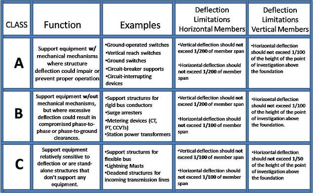
Structure Classifications & Deflection Limitations, Design Guide per ASCE 113
In substation design, there are three different structure classifications: Class A Structures, Class B Structures and Class C Structures. This is slightly different the old NEMA SG 6 that just had the substation structures broken out into only two classes: Class A and Class B. With ASCE 113, for determining the maximum deflections, they are broken down by horizontal members and vertical members. Horizontal Members are where the span of a horizontal member is the clear distance between connections to vertical supporting members, or for the cantilever members, the distance from the point of investigation to the vertical supporting member. To determine the maximum deflections, the span of a Vertical Member is the vertical distance from the foundation support to the point of investigation on the structure. The deflection to be limited is the gross horizontal displacement of the member relative to the foundation support.
As an experienced engineer, they understand that all structures should be designed to withstand applicable loads from things like wind, ice, line tensions, electrical equipment or other unusual service conditions when providing reliable structures for substation and transmission projects. Make sure to subscribe to the DIS-TRAN Blog today in order to receive next week’s article on loading criteria for substation structures.
Steel structures offer strength, durability, and long-term value. However, one of the biggest...
When partnering...
Transmission and substation structures can look straightforward at a glance. But the decisions...